As an ISO certified company, we have an obligation to investigate any of our product failures, but over the years we have been asked more and more to get involved in general failure analysis. We undertake to make an un-biased investigation into any failure involving cable joints and terminations regardless of who manufactured the product.
We received a report of a joint failure on an 11kV trifurcating transition joint (3 core pilc to 3 x single core xlpe cables). The joint was cut open along its length where some initial investigation had taken place. The external heatshrink shows no signs of any piercing damage which may have been caused by bad backfill materials during re-instatement. Joint shows signs of moisture ingress due to what appears to be a bad seal on the PILC end. Copper wire screens show signs of oxidisation due to moisture ingress.
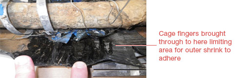
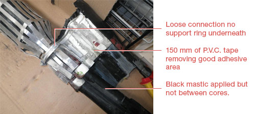
Seal on the PILC end could be better, P.V.C. tape applied round the dirty outer serving of the cable mastics then applied on top of this, no attempt to clean cable I would expect to see cable cleaned down to the hessian or armours to enable mastic to stick and provide a good moisture seal. A cage has been added for mechanical protection the connection of the cage would not be satisfactory enough for the passage of fault current. The cage extends past the earthing connection point on the PILC end limiting the outer shrink tubes ability to provide a good seal onto the lead and earthing connection point.
The joint has failed in the crutch area of the PILC side. Initial indications shows that grey mastic has been applied and shows no sign of moisture ingress through the earth braids or breakout itself. Further comment to be made later upon breakdown of this area.
As you can see from the photograph, the cage has restricted the recovery of the shrink tube onto areas were we would want it to obtain a good seal.
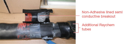
On the single core end a non-adhesive lined breakout has been used, although the jointer has tried to add extra moisture blocking by adding additional Raychem WCSM tubes also the breakout is not under the outer shrink as it should be. This may be because the jointer has used a semi conductive breakout and is trying to avoid earth contact in some way.
Removal of shrink over the sheath cut on the single core end shows the cage tightened down onto nothing therefore it is very loose, the whole area is covered in P.V.C. tape removing an adhesive area of nearly 150mm. No abrasion on the single core outer jackets. Some black mastic has been applied around the cables but none in the voids between cores.
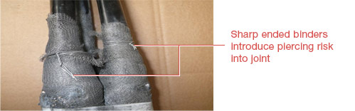
Braiding attached at the PILC end with a wire binder - these should be tied off. The binder is introducing a piercing risk into the joint. The braids should have been taken in an open weave up to the earth connection on the PILC end.
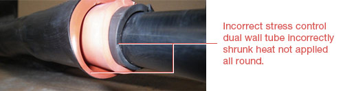
Most tubes appear to be shrunk correctly except the stress controls on all phases and the dual wall on yellow phase. Incorrect selection of stress control single core diameter is 22mm and this tubing will recover to 25mm.
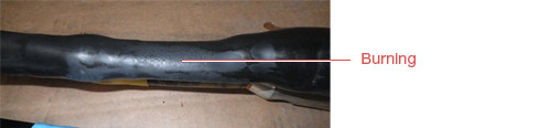
Burning can be seen on all three phases, extra heat has been applied to get the shrink to recover more than it’s capable of.
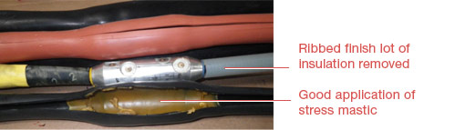
Stress tape applied at the polymeric screen cut and measurements adhered to. Taping over the connectors is good although has encroached onto the insulation by more than the 5mm suggested, would not be detrimental to the lifespan of the joint.
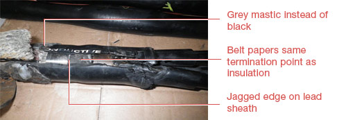
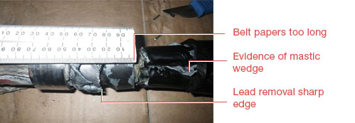
Sufficient grey mastic appears to have been applied under the breakout and there is evidence of a crutch wedge being installed. Belting papers have been terminated at the same distance as the insulation papers, 28mm from lead cut. Lead removal has left a jagged edge but has been “belled”.
Stress mastic only taken 20mm onto the lead sheath. Burning of braid, roll spring and lead sheath due to passage of fault current. Roll spring not tight enough and no PVC tape applied to keep it under tension also no copper mesh has been applied under the roll spring. Would have expected to see outer serving removed further back and the lead cleaned up for a longer length also jute removed from lead sheath.
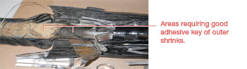
This all aids in the adhesion of the outer shrink and obtaining a good moisture seal.
Fault has occurred between red and blue phase in the crutch at the PILC end upon removal of the conductive tube on yellow phase it is apparent that the oil barrier tube is 15 mm up from the insulation papers. It should be as tight to the papers as possible to protect them from damage when they are spread for breakout fitting and jointing.
Oil barrier tubes on red and blue phase are 20mm up from the insulation papers.
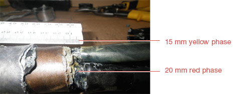
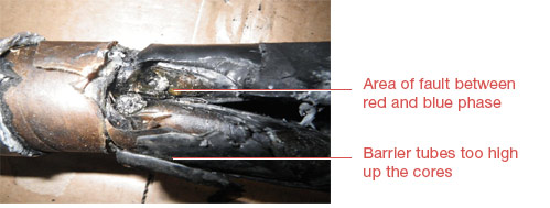
The cause of this particular fault is damage to the papers on red and blue phase this has probably happened when the breakout has been installed or when setting the cores for jointing.
Having fitted the oil barrier tubes a good distance from the crutch the papers in this area have not had sufficient protection when being manipulated, fracturing a few layers of papers in this highly stressed area will have a significant effect on the life time of the joint.
It is also apparent that a mix of 11 and 24 KV kits have been used for the completion of this joint combining material from one and measurements from another which is extremely bad practice. Correct joint for correct cable and voltage range should be used at all times instructions for these should be followed and not deviated from.
An 11kV 3 core transition joint which was audibly discharging.
View Case StudyJoint failure on an 11kV trifurcating transition joint
View Case StudyAn 11kV transition joint failed due to buckled armour cage
View Case StudyProblems with the earth continuity of a low voltage feeder
View Case StudyA cable box reported as "buzzing"
View Case Study